HDL Works

- Home
- Products
- Sales
- Support
- Company
- HDL Corner
HDL Works

A new utility in IO checker is the Symbol tool. It allows you to easily create symbols for an FPGA and export them to a schematic capture tool. This first version supports Altium Designer, Cadence Allegro, Cadence System Capture and Kicad.
The Symbol tool is a grid based tool in which each pin must be assigned to a symbol, a side and a grid location. It consists of a Symbol list, a Pin table and a Symbol (pre-)view. Using a wizard and the knowledge from IO Checker about the pins you can assign pins to a symbol and create a default layout for them in seconds.
The symbol (pre-)view shows you the resulting symbols and allows you to move pins and labels on that symbol.
The pin labels can be adjusted using regular expressions to remove characters not allowed in your schematic capture tool or truncate long labels.
More information about the symbol tool can be found here.HDL source
On the HDL page of the project properties dialog and in the project wizard you can select the VHDL and (System)Verilog language version you would like to use during the import of a top level entity or module.
PCB netlist patterns
The PCB netlist patterns page has been split in 2 groups: Units (reference designator) patterns and Nets patterns.
The new Ground and Power patterns offer an additional way to specify how to recognize these nets. For the Power net you can specify 2 captures from which IO Checker will determine the voltage value.
IO standards will be shown in the (red) error color when you set a standard that is not supported for the specified pin.
The text error color is also used in the HTML report of the project.
The ‘Restore location’ and ‘Restore IO type’ items in the context menu are only enabled when there is a value to restore.
The context menu items can now be activated on vector elements in the view.
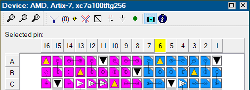
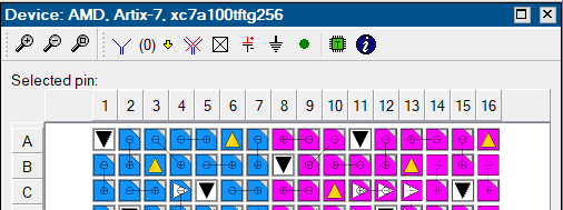
The device view can be toggled between top view and bottom view using the

 buttons.


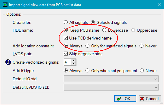
It is now possible to use the derived PCB signal names when importing PCB net names into the Signal view. The import dialog has been extended with a check box instructing IO checker to use the derived name. Select the rows in the pin view for which you would like to use the PCB derived name before starting the dialog.
The Default IO standards you can select are only set on the signal when the pin allows the standard (Only for Altera and AMD).

Individual pin IO standard information has been added to the device database for Altera (Quartus (Pro) 24.x) and AMD (Vivado 2024.2) devices. For these devices IO Checker verifies that the selected standard in the Signal view is indeed allowed on a pin.
Copyright © 2004 - 2025 HDL Works