HDL Works

- Home
- Products
- Sales
- Support
- Company
- HDL Corner
HDL Works

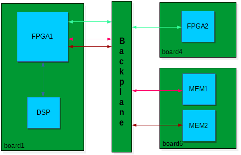
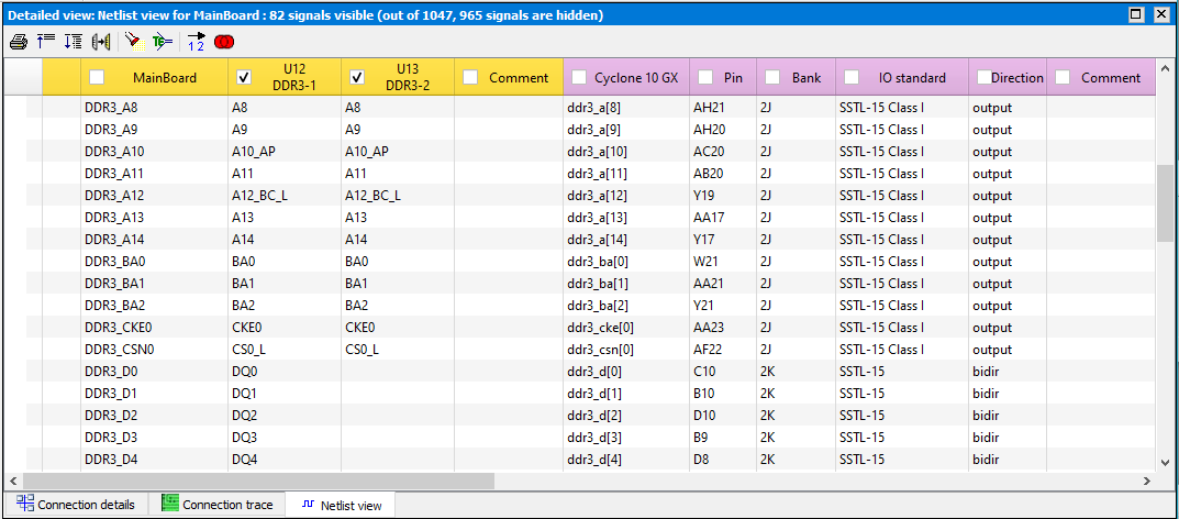
FPGAs on a board make verification even more complex. The programmable pins of an FPGA have generic names in the schematic capture, but the functional name will depend on the applied constraints. HDL Works has developed a way to visualize FPGAs in a system based on the pin report or constraint file of the FPGA vendor. Below is a (simplified) example of the tracing capabilities of BoardTrace. FPGA1 is connected to the component DSP (on the same board) and to FPGA2 (on board4) and MEM1 and MEM2 (on board6) through the backplane. You can add the pin file(s) of an FPGA and use this data to visualize how the user IO of FPGA1 connects to FPGA2, MEM1 and MEM2 on the other boards.

Each FPGA (for which you specify a pin file) is visualized as a virtual
connector (containing a pin for each pin present on the FPGA) and a virtual
netlist (containing the signal names used in the FPGA pin file).
Using this approach BoardTrace uses the FPGA functional (HDL) names (instead of
(often) generic net names on the board).

HDL Works recommends to use IO Checker to verify power and ground pins of an FPGA.
All device families from Altera, AMD, Efinix, Lattice Semiconductor and Microchip are supported in BoardTrace.
Connector adaptions
![]()
 Processors
Copyright © 2004 - 2026 HDL Works