HDL Works

- Home
- Products
- Sales
- Support
- Company
- HDL Corner
HDL Works

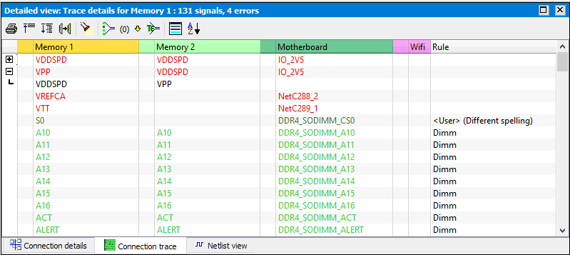
The connection trace shows all nets of a selected board that connect to one of the other boards in your project in a large table. Signals that fail the matching test are displayed using a red color. BoardTrace also shows which signals in the netlist get connected to each other when the board is part of a system.
BoardTrace recognizes power and ground nets, pull-up and pull-down resistors in the netlist and shows the appropriate circuit type in the trace view (combined with the pull-up voltage). This makes it easy to see if different pull-up voltages have been used, or a voltage divider is created when connecting 2 boards. It can also look-over resistors when internal net names are used.

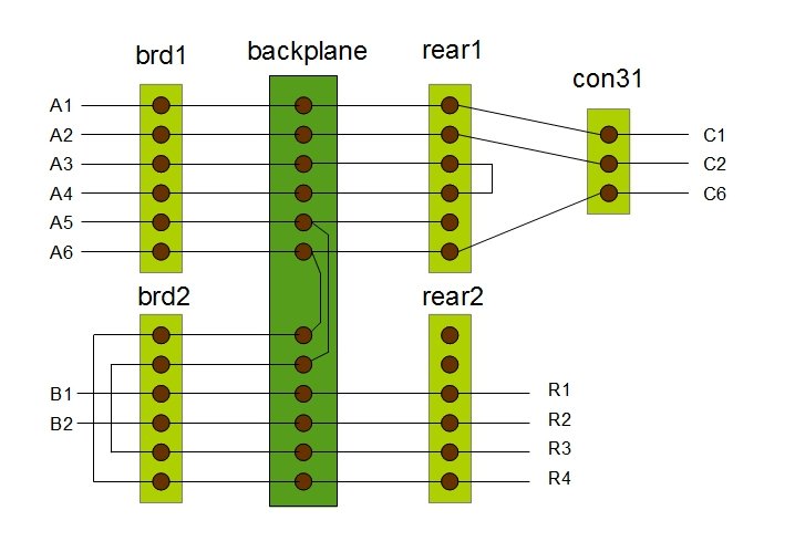
The figure below is a simplified example of the kind of connectivity tracing
BoardTrace can perform.

BoardTrace will show that:
A3 is connected to A4 when Brd1 is placed in the system
A1, A2, A6 are connected to C1, C2 and C6
A5 and A6 are connected to R3 and R4
B1 and B2 are connected to R1 and R2
Connectivity errors in a backplane design can sometimes be hard to locate when signals connect to multiple pins on different connectors. In the screenshot below you can see that the signals 'xCheck' and 'GND' on 'Brd7' become connected when the board is placed in the system. With the 'Show path' command you can easily determine how problem occurred.


Pin labels
![]()
 Connector
transformations
Copyright © 2004 - 2025 HDL Works